
Virginian Research
From the Railroad Gazette, March 13, 1908, pp. 348-352
Station Standards; Virginian Railway
In the previous articles (see Railroad Gazette of March 15 and August 23, 1907, under caption “The Tidewater and the Deepwater Railways”) the general features of the road and the methods of track and bridge construction were considered. The same system of standardization that has already been outlined has been carried on to other departments of the work.
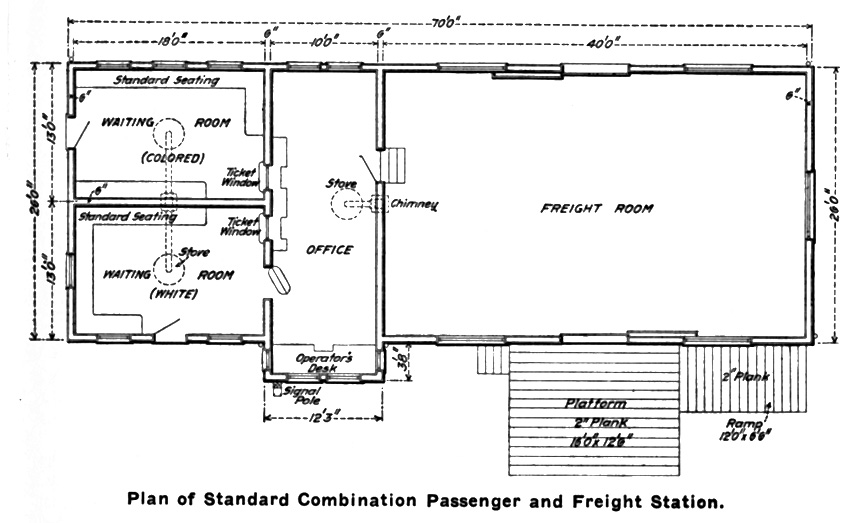
It is not often, however, that railroad standardization is carried to such an extent as to include the station buildings and section men’s houses, so that they can be built and located where desired, without further attention from the engineering department. This has been done in this instance, and is working successfully. The plans, as prepared, could only be made applicable to places where the conditions to be met are practically uniform; but as there are no large towns along this line, the plans are applicable to nearly every place upon it. The original plans were of three main types; one for towns of considerable size; one for small places in Virginia, and one for small places in West Virginia. Later it was found that a modification of these would be required in certain localities. For example, new stations were designed for use in the tobacco section of Virginia for both large and small towns; and, in West Virginia there has been a revision of the plans for small towns. The reason for the distinction made between the two states is that the laws of Virginia require separate waiting room accommodations for white and colored people, while those of West Virginia do not. The first design of station for large towns is 80 ft. long by 22 ft. wide. The second is 70 ft. long by 26 ft. wide, and both are combination freight and passenger stations. The original station for small Virginian towns contains waiting rooms for white and colored passengers and a ticket office and a freight house and measures 60 ft. by 22 ft. That for West Virginia has but one waiting room, the ticket office and freight house, and measures 40 ft. by 16 ft.
Of the smaller sized stations of the original design that at Mullens, W. Va., is typical. It is a frame building and the specifications permit that the rough framing shall be of either white, Norway or southern pine, spruce, Pennsylvania white hemlock or fir, provided only that it is sound and free from defects. The interior finish is in natural wood, kiln dried and varnished on the exposed surfaces. The flooring of the offices and waiting rooms is of quarter sawn Carolina pine or maple of 2 1/2 in. face and 7/8 in. thick and matched for the whole length. The baggage and freight house flooring of all stations is of 2-in. southern pine 6 in. wide, quarter sawn and smooth. The exterior is given three coats of standard paint, one priming coat and two finishing coats, the body color to be a standard light yellow with white trim. Six settees are provided along the walls of the waiting rooms, and these are made of 7/8-in. oak or ash slats with V joints screwed to cast-iron brackets or supports of the form shown. These specifications as to finish also apply to the larger sized stations.
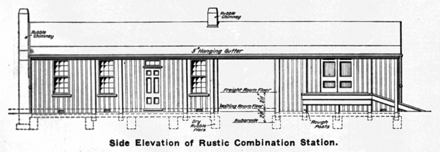
In the Mullens and similar stations the waiting room has an inside measurement of 10 ft. by 14 ft. 10 in., or the full inside width of the building; the ticket office has a width of 6 ft. 6 in. and the freight house 21 ft. 4 in. The latter has sliding doors at the front and back and, on the track side, has a gangway of 4-in. planks for an approach. In the second design of “rustic stations,” as they are called, the total plan of the building covers an area of 62 ft. by 16 ft. with an operator’s window at the ticket office end projecting 5 ft. 6 in. on the track side. This projection is merely the extension of the ticket office out to the edge of the overhang roof of the platform. This roof is carried at its outer edge by eight round wooden columns. The ticket office at one end has a width over the partition walls of 11 ft. and extends the whole width of the building. The total length of the ticket office and waiting room section of the building is 34 ft., of which the waiting room occupies 23 ft. Beyond this is an open driveway 11 ft. wide and then a freight room occupies the remaining 23 ft. of the plan. The floors of these freight rooms are either on the ground or raised 2 ft. 11 in. above the level of the waiting room floor. The intention is to use the rustic station with an elevated freight floor in the tobacco country of Virginia, while that with a low floor will be used in West Virginia. The interior finish of these stations is essentially the same as that of the design already described. Externally they have a rubble chimney for both the ticket office and waiting room, which gives them the characteristic feature of the other building of the country, and it is the intention to plant climbing vines about the one at the end of the building. This will be an innovation and add to the attractiveness of the structure.
The floor plan of the 60-ft. by 22 ft. station for small towns in Virginia is the same as that of the larger 80-ft. by 22-ft. station except in dimensions, and the inside and outside finish is like that of the smaller West Virginia stations.
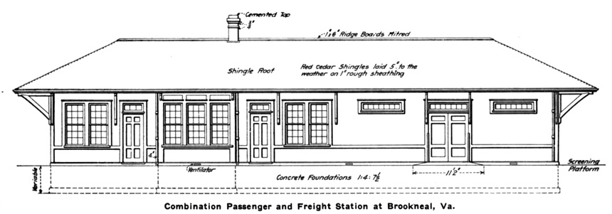
The 80-ft. by 22-ft. station, of which that at Brookneal, Va., is a sample, has a freight room at one end 34 ft. 6 in. long and two waiting rooms for white and colored people respectively, each with a width of 21 ft. 9 in. at the back and 16 ft. at the front, where the ticket office is located. In modifying this design, the building has been widened to 26 feet and the waiting rooms placed one back of the other at one end of the building with the ticket office between them and the freight room. These stations are also frame buildings erected to the same general specifications as the smaller stations and with the same interior and exterior finish.
In addition to these regular stations that are to be built in towns and villages, a smaller building known as an operator’s house has been designed for use at points where it will be necessary to make station or water stops and where no freight will be received. Such a place, for example, as Elmore on the Deepwater section where there will be an assembling yard and water tank. Here it will be necessary to have an operator and accommodations have accordingly been provided for such passenger traffic as may offer. The outside dimensions of the building are 12 ft. by 30 ft., and it is divided in the plan into two rooms; one a waiting room and one for the operator. The interior and exterior finish is the same as that of the standard stations, and it has the same large opening between the two rooms filled with a wire mesh that obtains in the case of the other buildings.
This standardization of station buildings is possible, of course only for small towns. For large places special designs would have to be prepared, and this has been done in the case of the road in large places, Norfolk and Roanoke. Here there will be a yard and a freight house of dimensions suited to the requirements of the cities. The passenger stations have not yet been designed.
The layout of the tracks and building is given on the plan. These are located at the south side of the city at the crossing of the Roanoke & Southern or the Winston-Salem division of the Norfolk & Western. The passenger station will be 40 ft. wide by 150 ft. long and will be approached by a screening driveway from Jefferson avenue along which there is a line of street cars. This street will be raised about 5 ft. to meet the grade of the road. The road is single track and will have a connection with the Norfolk & Western over a 13-deg. curve, and there will be a long passing siding in front of the depot, with a track leading off to a double-track siding in front of the freight depot with space left for additional tracks when the traffic offered may require it. Beyond the freight house there will be a number of team tracks as shown. In all of this layout the plans have been prepared for present construction and future extension.
The freight depot, as designed, will have a width of 40 ft. and a length of 231 ft., of which but 134 ft. 11 in. will be built at present, and the remainder added when the requirements of the traffic shall demand it. The part to be built first will be the east end and will include the offices. The building is to be of brick set on concrete foundations of 1-4-7 1/2 mixture except around the basement beneath the offices, where a 1-3-6 mixture is to be used. Provision is made in these foundations for expansion and contraction due to variations of temperature by the use of vertical tarred paper joints. The piers for the posts supporting the freight house floor are also of concrete of the 1-4-7 1/2 mixture, and these are spaced on 9 ft. 6 in. centers longitudinally and 9 ft. 5 in. centers transversely. Everything is carried down to at least a foot below the natural surface of the ground, or as much lower as may be required in order to get a good footing. The floor of the freight house is carried on 12 in. x 12 in. posts capped by 12 in. by 14 in. girders, upon which 2 in. by 12 in. joists are laid on 12-in. centers, over which the 2-in. flooring is laid. The top of this floor will be 4 ft. 6 in. above the base of the rail and will have a drop of 2 in. in the slope of the outside platform, so that the latter will be 4 ft. 4 in. above the base of the rail. This platform, which will be on the track side only, will have a width of 8 ft. 2 in. The sliding doors opening upon the platform will be spaced on 38-ft. centers so that a string of five cars can be spotted in front of the house, each with its door opposite one in the house. Scales will be placed near the center of the floor of the first section to be built, and this will be completed with a brick end wall, which will afterwards form a brick firewall extending up through the roof.
A basement with a headroom of 8 ft. will be located beneath the offices and will be used as a heater room. The floor of this space will be of waterproofed, reinforced concrete on a screening foundation, the whole having a thickness of 21 in.
The roof is carried by a simple wooden truss and the whole floor space will be clear and unimpeded by columns. These trusses are spaced on 19-ft. centers. Skylights are put in each slope on 38-ft. centers so that there is ample light admitted from above. The curbing around these skylights is to be of white pine with wooden bars glazed with 3/8-in. ribbed plate, shingled and set in putty with clips. The roof covering will be of No. 1 American Bangor slate laid with a 3-in. lap.
The drainage of the roof water is provided for by five downspouts on each side. Those on the track side deliver into a 6-in. vitrified sewer pipe that leads down the side of the building to the ends where it empties into 8-in. pipes that run across the ends of the building into a sewer opposite the center of the building and set some distance out from it. At the back corners where the 8-in. pipes turn from the ends, lamp or cleaning holes will be placed, and at the sewer opening there will be the usual manhole and cover. In this way the water from the roof is led away from the foundations at once and the seepage of dampness beneath the building will be avoided, as the pipes are run at a minimum distance of 4 ft. from the walls.
The offices are to be finished in natural wood, with rubbed down shellac, followed by two coats of hard oil rubbed down to an eggshell gloss.
This is the only large freight house that has, thus far, been designed, as there is no need of so extensive a provision at other points along the line. Work is also in progress on the yard that will be located at Roanoke.
Roanoke Yard. -- This yard is the only one of any magnitude that has, thus far, been designed, and even this is small in comparison with other distributing and classification yards that have been built in recent years. The reason for this, at so important a point as Roanoke, is that the traffic that is expected will consist almost exclusively of coal bound for tidewater and originating on the Deepwater section. This traffic will be made up and classified in the Princeton yard, which will be the main point of assembly for the road as well as that from which the empties will be distributed among the mines. Hence both east and westbound trains will for the most part pass through Roanoke without breaking bulk.

(click on the image for a larger view)
The total length of the Roanoke yard is about 7,800 ft. and it is located almost entirely west of the passenger station at Jefferson avenue. The layout is somewhat peculiar and is based upon the exigencies of the case and the topographical limitations imposed. In general the yard follows the bend of the Roanoke river, whose banks it reaches a short distance west of the roundhouse. On entering from the east there is a lead from the main line to the left which runs parallel to the same for the whole length of the yard and forms a passing track. Before reaching the passenger station there is another lead to the left which branches into the double track in front of the freight house already referred to with two extra tracks that may be used for storage. The total capacity of these four tracks from a point east of the freight house to the switches giving access to the team tracks is 114 cars. This team track yard is placed between the freight house and the storage yard and is arranged with double blind-end tracks with a screening driveway approach to one side of each track. These have a total capacity of 126 cars, and beyond, between the team tracks and the roundhouse, is a storage yard composed of 18 blind tracks served by a single ladder track and having a capacity of 300 cars. As will be seen from the engraving, the switching lead for all of these tracks is one running parallel to the main line and extending down into the eastbound yard, where it is to be used as far as the necessities of the string of cars being handled will require.
The roundhouse is to be in the angle formed by the line of Jefferson street and Prospect avenue. At present a house of 10 stalls will be erected but provision will be made for extending it by 20 stalls, making it 30 in all, as soon as it may be needed. The coal trestle, water column and sand pockets are placed between the incoming and outgoing tracks, with ash pits set in the incoming tracks, and these are doubled at that point. The coal pockets have a length of 200 ft. and stand 30 ft. above the tracks, being reached over a trestle on a 5 per cent. grade.
The repair tracks are south of the approach tracks to the roundhouse and are served by a single ladder track that is extended by a switching lead running along the southern side of the main yard and connected with it in such a way that cripples can be taken to the yard and the repaired cars removed and placed in either the east or westbound yards without interfering in any way with the engine movements to or from the roundhouse.
Next to the repair tracks come those for cabooses and the wrecking train. This arrangement of caboose tracks necessitates special switching for the caboose both on incoming and outgoing trains in each direction.
The neck of the yard is formed below the Franklin Road bridge, which is about 3,000 ft. west of the eastern end of the yard or near the middle of the same when it is considered as a whole. At this point there are live tracks; that on the north is the main line, then comes the passing track, then two crossovers and engine tracks, and last the switching lead for the repair tracks.
The east and westbound yards lie side by side and, except for the arbitrary assignment of tracks to the two, are essentially a single yard consisting of 14 tracks exclusive of the running track at the south side and the passing track at the north, and having a common ladder at each end, that at the west end being run into the passing track and then used as a switching lead. The total capacity of the yard is 1,128 cars, of which 1,385 are assigned to eastbound and 743 to westbound traffic.
The movement of the cars through the yard will be very simple in that, as already explained, there will be very little breaking up of the trains. On entering from the west the trains come in over the passing track and switching lead and in upon the eastbound tracks. The engine is cut off from the train and passes on directly to the roundhouse. The caboose is cut off and hauled back and thence around the running track to the south to the caboose tracks, and whatever classification may be needed will be done over the latter at the east and the running track extending down past the freight station, the cripples being taken out and dropped in on the repair tracks to which a direct lead is provided by way of the ladder from every track in the yard.
Entrance to the westbound yard is effected in a similar manner. The train leaves the main line at the first switch and runs over the passing or running track by way of the cross-overs beneath the Franklin road bridge to the yard ladder and thence in upon the westbound tracks. The engine returns to the roundhouse over the running track to the south of the yard and the caboose is cut off and hauled directly back upon the waiting tracks. Classification and the cutting out of cripples is accomplished in the same manner as in the case of the eastbound traffic.
From east to west the yard grade is level as far as the station when it begins to rise and continues to do so to the western extremity at a rate varying from 0.20 to 0.358 per cent.
The yard is in no sense a classification yard although some work of that character will necessarily be done there, but it is more of a halting place where engines can be changed and cars inspected and repaired prior to their onward movement to tidewater or the mines. For this reason a complication of operation is not provided for as it will be in the case of the great assembling yard at Princeton, which will be dealt with at length in a future issue.
Miscellaneous Standards. -- In connection with the station and yard work certain other standards have been adopted that are based upon good American practice and which will serve to simplify the work of the engineering department as already intimated. Among these are standards for water tanks, signals, turntable foundations, crossing signs, methods of running wires, fencing, towers, etc.
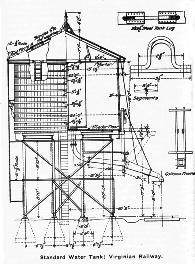
One example of these standards is given in the 16-ft. by 24-ft. water tank having a capacity of a little less than 52,000 gallons. As in all other foundation work concrete is used for these tanks. In this case the proportions being 1-3-6. Ordinarily the footings are 4 1/2 ft. sq. but these are increased where the soil is soft. All of these columns are formed of 6 in. by 6 in. by 1/2 in. angles rising to a height of 17 ft. 9 in, above the rail and there carrying the floor beams, which are made up of 12 in. I’s with 8 in. I beam braces. The floor of the tank is made of 3-in. cedar plank, and its upper surface is 7 in. above the tops of the columns, so that it is 20 ft. above the top of the rail. In the general features of the construction the tank does not differ essentially from others of a similar character and is illustrated as an example of good current practice.
With the design adopted the only flexibility required is in the adjustment of the foundations to the soil upon which they stand, and the same holds true of those for turntables. In that for the 80-ft. table, which is the size adopted, the engraving shows the center arranged to be carried on piles, and these are ordinarily calculated to carry 15 tons. The concrete is of the 1-3-6 proportion as in the case of the water tank piers, and is reinforced with 1-in. square rods spaced on 12-in. centers and in two rows which are 3 in. apart horizontally; the lower rows being 6 in. above the tops of the piles when these are used and projected 12 in. into the concrete.
When piles are not used the lower row of reinforcing is placed 6 in. above the bottom of the concrete, and when the concrete is carried down to a rock foundation the reinforcement is omitted. The foundation is finished with a cap of richer concrete of the C class or 1-2-2 mixture 18 in. thick, upon which the base of the center is to rest.
In the matter of signals the final decision has not yet been reached as to what will be done all along the line, except that it is probable that some system will be adopted whereby a space interval can be maintained between trains. Meantime the details of the signal posts and semaphores have been worked out in accordance with standard practice, being identical with that adopted on the New York Central lines.
In working out these standards allowance had to be made in some cases for the variations in the laws of the two states through which the road runs. These usually make themselves felt in minor details but are of sufficient importance from a legal standpoint to make themselves felt. For example in the case of crossing signs. In Virginia the simple wording “Railroad Crossing” suffices, but in West Virginia there must be added to this the words “Look Out for the Locomotive.”
From what has been said in this and previous articles it will be seen that thoroughness in all of the details that go to make up the sum of the construction of the road from the preliminary surveys to the construction of the buildings and tracks has been the watchword of the management throughout.
It now remains to say a few words regarding the terminal facilities at the coast. It will be remembered that this road is built with the intention of building up a traffic that does not yet exist and of developing coal properties that have not yet been fully opened.
(click on the image for a larger view)
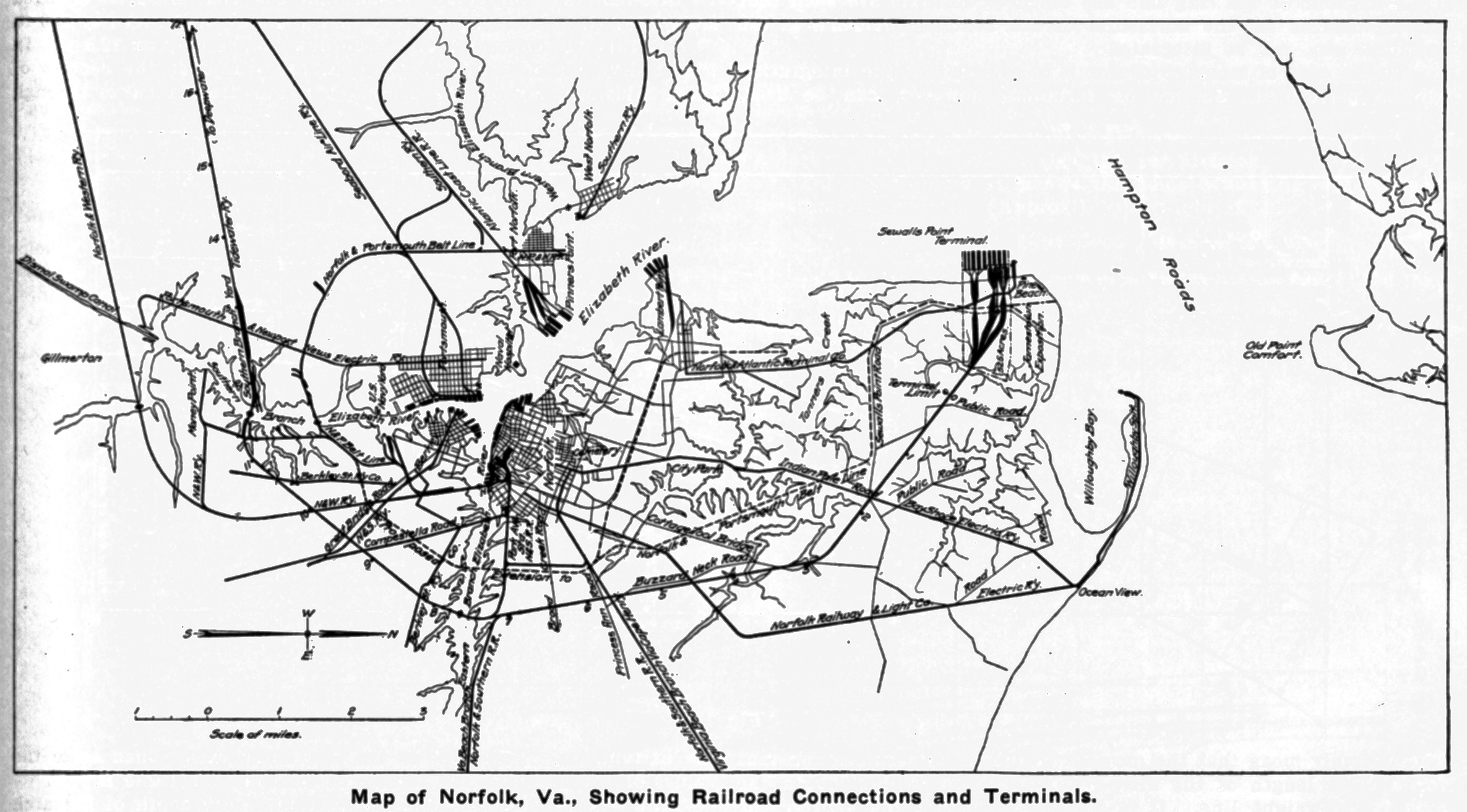
Further, as there is no market for this coal along the line of the road and the outlet to the west is restricted, it is evident that the seaboard must be the destination of practically all of the traffic that will originate along the line, and that provision must be made to handle it in a coastwise traffic. For this reason no attempt has been made to enter Norfolk over its own lines, but on the other hand, a wide detour carries the line well beyond the limits of the city and around to the north of the same to the terminal at Sewall’s Point. Before reaching the Elizabeth river it runs parallel to the Norfolk & Western, but about two miles to the north, thus skirting the Dismal swamp. A yard will be located on the west bank of this southern branch of the Elizabeth river at the point of crossing of the Portsmouth & Newport News Electric Railway, beyond which it crosses all of the roads centering in Norfolk and then runs down on the sand spit that forms Cape Henry and so reaches Sewall’s Point. This point is opposite Old Point Comfort and borders the deepwater of Hampton Roads, but is still sufficiently sheltered to make it possible for vessels to lie securely at the wharves that will be built, without experiencing any inconvenience from the seas that may roll in from the capes outside.
The terminal property as acquired by the railroad was a barren stretch of sand, and on this the heavy wharves and coal handling apparatus will be built. Soundings have been made to determine the qualities of the underlying ground and it is probable that the methods of transferring the lading from the cars to the steamships will be similar to that used upon the lakes, where the cars are lifted and dumped into the hold or weighing hoppers direct without the use of the conveyors or hoists that usually accompany coal-handling plants. It is thought that these car dumps can be made of greater capacity and can handle a large tonnage more expeditiously and economically than a trestle and incline, and for that reason it is probable that they will be adopted. The road will thus be a further exemplification of the predominance of the progressive ideas which It has been shown have controlled every step in its construction from its first inception to the completion of those facilities that will play so important a part in the delivery of its traffic to the markets of the country.