(From Railway Age Gazette, Vol. 54, No. 25, June 20, 1913, pp. 14-19.)
Ninety-Ton High Side Gondola Car.
Developed on the Norfolk &. Western and With Specially Designed Six-Wheel Equalized Equipped Trucks.
Cars larger than 120,000 lbs. capacity, if mounted on four-wheel trucks, involve pressures on the journal bearing which cause a large increase in the troubles with wheels and axles, as well as requiring much closer attention to prevent hot boxes. It therefore seems advisable to use six-wheel trucks under cars of extra large capacity. A six-wheel truck, as constructed for passenger ears, has been considered too expensive and complicated for satisfactory use in freight service, and with the exception of a few special cases, has not been so employed. When cars as large as 90-ton capacity, considered in connection with the usual 10 per cent. overload requirement, are to be built, a six-wheel truck is practically compulsory, and in connection with the design of such a car on the Norfolk & Western, the problem was solved by the development of an entirely new type of six-wheel truck, which permits the use of the ordinary 5-1/2 in. x 10 in. M. C. B. journal box, while at the same time the weight is properly equalized and the truck is given the necessary flexibility.

Ninety-Ton Gondola Car Mounted on a New Design of Six-Wheel Truck.
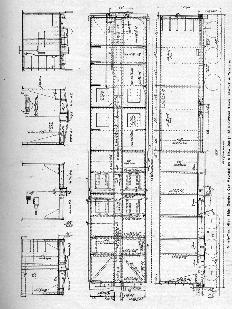
These cars are of the high side gondola type and measure 9 ft. 6 in. in width, 6 ft. 6-1/2 in. in height and 45 ft. 6-1/4 in. in length on the inside of the body. This gives a cubic capacity of 2,829 cu. ft. level full, and 551 cu. ft. in a 30 deg. heap, making a total of 3,390 cu. ft. Pocahontas run of mine coal is taken at 58.85 pounds to the cubic foot. The first load of coal hauled in the car was 95 tons, with some corners not quite filled out. The maximum outside dimensions are 48 ft. 4-7/8 in. over bumping blocks, 10 ft. 4-1/2 in. to the top of the side of the light car, 11 ft. 1 in. to the top of the brake shaft and 10 ft. 4-1/2 in. extreme width over the body. The cars are provided with eight small drop doors in the floor, which are operated by a simple type of winding chain and shaft mechanism. The design is of the continuous center sill type. Cross beams or diaphragms are introduced to prevent deflection of the center sills, which, in a car of this length, would prove serious. This results in transmitting the load to the sides of the car which carry it, as plate girders, to the bolsters, whence it is transferred to the center plates. The stakes are on the inside and while interfering to a limited extent with lading other than coal, ore, or similar material, have a number of advantages. With outside stakes, the punching of the upper flange of the side of the car for rivets detracts materially from the strength of the section, this portion being in tension; while with inside stakes the rivet holes are on the compression side of the member. It has also been possible, with inside stakes, to do away with body cross ties, which are undesirable and form a fertile source of repair bills. Inside stakes are of particular advantage in this case, inasmuch as they form the means of powerful side stiffeners near the top chord angle of the side plates. As this car has been designed for use in a dumping machine, it will be readily seen that such construction is necessary.
Commercial shapes are largely used, special castings being incorporated at a few points only. The center sill consists of two 15 in. 33 lb. channels which are continuous for the full length over end sills. These are set 12-7/8 in. apart with the flanges extending outward and a 5/16 in. top cover plate extends continuous between the bolsters. The edges of the 1/4 in. floor plates extend under this cover plate and are secured to the center sills by the same rivets. At the double body bolster there is a 1/2 in. plate 38 in. in width, and extending across the car, which forms the floor at this point. Between this and the end of the car the center sill cover plate is 1/4 in. thick. At the bolster the center sill is reinforced at the top by 3-1/2 in. x 3-1/2 in. x 1/2 in. angles arranged as shown in the illustration. The three cross bearers each consist of a 3 in. x 2-1/2 in. x 3/8 in. angle continuous under the center sill and secured to the bottom of the side posts at either end. They also include a 1/4 in. web plate on either side between the center sill and side. This plate is made in two parts, the outer end for a distance of 20-1/4 in. consisting of an extension on the wing or gusset plate which is carried nearly to the top of the sides. The remainder is a properly shaped plate which extends only to the floor. The joint between the two is made with a splice plate 1/4 in. thick. The top member of the cross bearer consists of two 2-1/2 in. x 2 in. x 1/4 in. angles extending between the center sill and the side plate. The floor plates are of such a size that the joints come at the cross bearers and the edges are riveted to the angles.
Midway between the cross bearers and also between them and the bolsters are floor beams, consisting of 8 in. 11-1/4 lb. channels with the outer ends riveted to the bottom of the side posts and the inner ends secured to the center sills through the medium of 1/4 in. gusset plates and angles fastened on the webs of the center sill channels. The smaller wing or gusset plates are located above these floor beams and consist of triangular 1/4 in. plates about 28 in. wide at the bottom and about 31 in. high riveted to the side posts and secured on top of the floor plates by angles of the proper length, the rivets holding the angles also extending through the flanges of the channels which form the floor beams. At both the floor beams and cross bearers there is a short reinforcing angle riveted to the top cover plate of the center sill, which is also the floor plate.

(click on the image for a larger view)
Ninety-Ton, High Side, Gondola Car Mounted on a New Design of Six-Wheel Truck; Norfolk & Western.
In view of the large weight concentrated at the center plate it was necessary to design a bolster of unusual strength and rigidity which would properly convey the load from the side girders, which carry the greater portion of it. Practically two bolsters, set 36 in. apart, have been employed and a large casting fitted between the center sill channels connects the two and includes the center plate. Each of these bolsters consists of a 1/2 in. web plate and a pair of 4 in. x 3 in. x 3/8 in. angles at the top. Similar angles at the bottom, which in both cases extend only from the side plate to the flange of the center sill channel, are also used. A 3/4 in. plate, 16 in. in width at the center and tapering to a width of 8-1/2 in., extends under the center sill and the center plate casting and is riveted on either side to the flanges of the bottom angles. At the junction of the side plate and each of the bolsters there is a jacking casting, formed to fit around the bottom end of the side post and strengthen the construction at this point. This gives four jacking points at each end of the car. A 1/2 in. top cover plate of sufficient width to include both parts of the double bolster extends across the car and is secured to the side plate by an angle. The side bearings are attached to a properly shaped casting forming a bridge between the two bolsters and are located at a radius of 3 ft. 9-1/2 in. from the truck center.
A large proportion of the load is carried by the sides of the car which consist of 1/4 in. steel plates 87 in. in width and 138 in. in length. The vertical joints between these sheets are made by 1/4 in. splice plates on the inside, and the double stakes at these points are set in enough to allow for them. This plate girder, of which the side plates form the web, has a 5 in. x 3 in. x 7/16 in. angle at the bottom with the flange extending outward, and a 5 in. x 3-1/2 in. x 7/16 in. angle at the top. Both angles are continuous for the full length of the car. There are no diagonal braces and the plate is stiffened by the 4 in. x 3 in. x 1/8 in. angles forming the stakes, which are spaced as shown on the drawings. These angles continue to the bottom of the side plate and are fastened to the cross bearers and floor beams. As before mentioned the wings or gussets of two different sizes form the principal source of stiffness for these girders.
The construction at the end is practically the same as at the sides. The comer posts, however, are 3-1/2 in. x 3-1/2 in. x 3/8 in. angles. The end sill is of oak 8 in. x 9-1/4 in. and the center sill channels are cut out at the top sufficient to allow its introduction. The end sheet of the car extends behind the end sill which is also reinforced by the end posts and the angle to which the floor plates are secured.

(click on the image for a larger view)
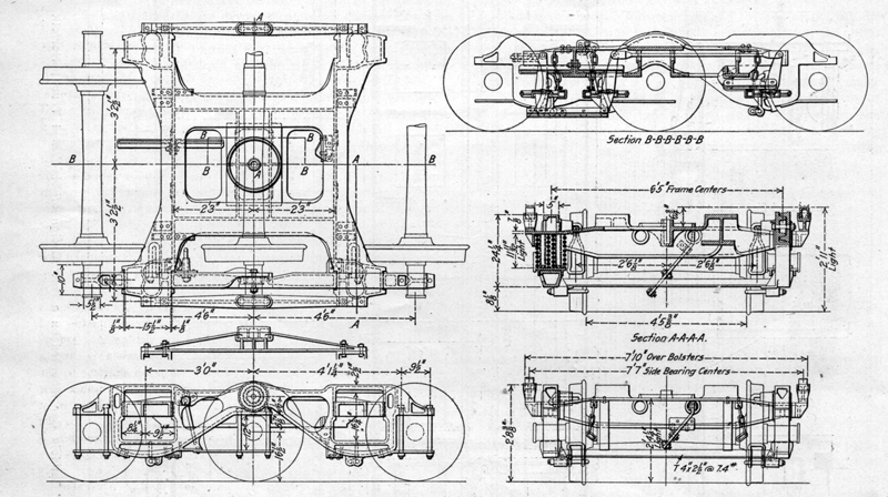
Six-Wheel Equalized Truck with Journal Boxes Secured to the Side Frames; Norfolk &. Western.
The car has a Miner friction draft gear with Miner attachments. It will be seen that the gear is attached directly to the center sills with the usual reinforcing castings on the webs and that the coupler yoke passes below the wooden end sill, the carrier iron being bolted to the bottom flanges of the center sills. The rear casting of the draft gear has a minimum clearance of 1/8 in. from the extension on the center plate casting. The center of the line of draft is 3-3/4 in. above the bottom of the center sill channels.
Each car has two sets of brake rigging, including auxiliary reservoirs, triple valve, brake cylinder, etc. The reservoirs are supported below the center sills just inside of the truck and the train line passes between the two center sill channels for the distance between the bolsters. At the bolsters and to the end of the car it runs outside of the sills. The brake cylinders are located just under the end sill, there being one at either end of the car connected to the adjacent triple valve and reservoir. The hand brake is located on the opposite side of the car from this cylinder and connects to the opposite end of the same brake lever. This location of the brake cylinder is somewhat in the nature of an experiment and arrangements have been made for placing the cylinders between the trucks at about the usual locations if the present location should prove unsatisfactory.
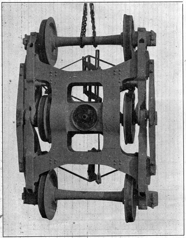
A six wheel equalized truck without pedestals is a novelty and has been developed for use on this car by W. H. Lewis, superintendent of motive power and John L. Pilcher, mechanical engineer. It consists of a cast steel side frame in two parts and of peculiar shape arranged to carry three journal boxes at 4 ft. 6 in. centers. Directly above one of the journal boxes the castings are arranged for a swivel connection. In these two castings the openings for the ends of the bolster and for the group of coil springs are spaced at 3 ft. centers from the center axle, bringing them 18 in. from the outer axles. One of the illustrations clearly shows the form and arrangement of the double cast steel bolster which carries the center plate. This rests on four nests of three double coiled springs each and has an extension beyond the side frame to allow the attachment of a bridge which carries the side bearing at the center of the truck. This bridge is bolted to the bolster extensions. Each group of springs consists of three nests of an outside coil of 1-1/4 in. diameter wire, 5 in. outside diameter, with an inside coil of 9/16 in. wire, 2-1/4 in. outside diameter. The springs work at 40,000 lbs. stress in the bar when the car is loaded to a 10 per cent. overload. The free height is 11-1/2 in. with a total deflection, free to solid, of 1-3/4 in. The swivel joint in the side frame is so formed as not to give any shearing action on the bolt. This arrangement is shown in the sectional view through the center of the truck. This view also shows that the bolster is not as heavy as it might appear in the photograph. There are two 4 in. x 2-1/2 in. tees bolted to suitably formed lugs on the bottom of the side frames and located midway between each of the pairs of wheels. These take the place of sand planks which are not feasible when the bolsters are arranged in respect to the wheels as they are in this case. It is possible that these cross ties may be omitted altogether. Tests will be made to determine this.

Top View of the New Six-Wheel Freight Car Truck.
The brake rigging on each truck is comparatively simple and arranged in a manner similar to a six-wheel passenger truck. Designs for carrying the brake beams from either the side frame or the bolsters have been prepared. The one given here shows the former. This truck has been patented by Messrs. Lewis and Pilcher.
The weight of the two trucks alone is 29,800 lbs., and of the car complete with trucks is 65,200 lbs., giving a total weight with lading, including a 10 per cent. overload, of 263,600 lbs., or an average weight per axle at the rail of slightly less than 44,000 lbs. With a 10 per cent. overload the proportion of revenue lading to total weight will be about 75 per cent., and it will be over 73 per cent without the overload. It is expected that it will be possible to reduce the weight slightly, especially that of the trucks in later cars.
The entire car has been carefully designed with a view to ease of manufacture. To this end all plates and shapes are laid out for multiple punches, and care has been taken that if the plates, etc., come within the customary variations in shearing, no reshearing will be necessary. Duplication of parts has been carefully considered with good results.
